For the 2016 racing season, I decided to completely re-wire my buddy’s Mustang from front to back. I originally wired the car in 2012 on a shoe-string budget and a huge time constraint. Over the past few seasons, we made multiple changes to the car including a few different engines, different ignition systems, different nitrous systems and controllers, etc. Needless to say, the wiring was starting to look even worse than it was to begin with.

At the heart of any purpose-built racecar’s electrical system is the relay/fuse panel. In this particular instance, it powers the ECU(Engine Control Unit), ignition coils, nitrous system, trans-brake, purge solenoid, and provides a switched 12-volt power source.
It’s important that the fuse/relay panel is accessible and easy to troubleshoot and/or modify quickly. Often times, we have very limited time in between rounds to sort out an electrical problem or make changes to the wiring.
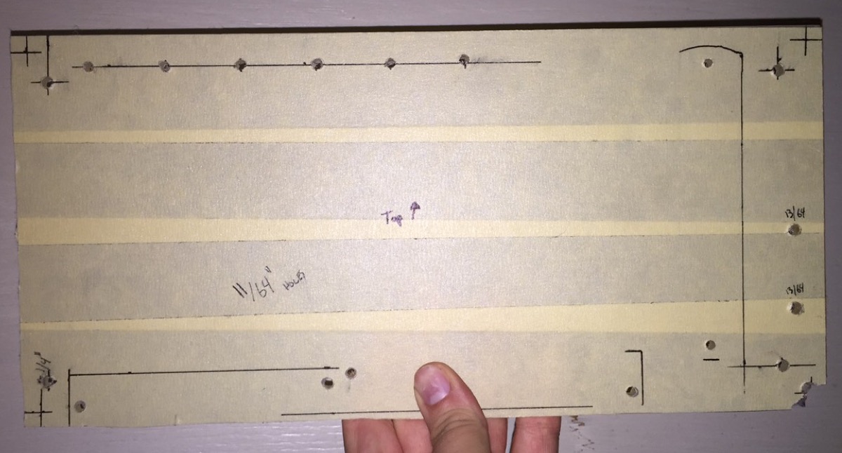
Keeping this in mind, I began to lay out the components on a .220″ acrylic panel. I’m using two 10-position screw terminals – #6 for low-amperage switch inputs, etc – #8 for high-amperage power outputs. These screw terminals will make it easy to attach the wiring in the car to the panel. It will also make it easier to change the wiring as the components in the car are upgraded.
I’m also using six 40-amp relays and a fuse-block that features a single 4 AWG input and nine #6 screw-terminal outputs. This fuse-block makes power distribution and adding fuses to circuits so much easier, as well as making everything a bit neater.
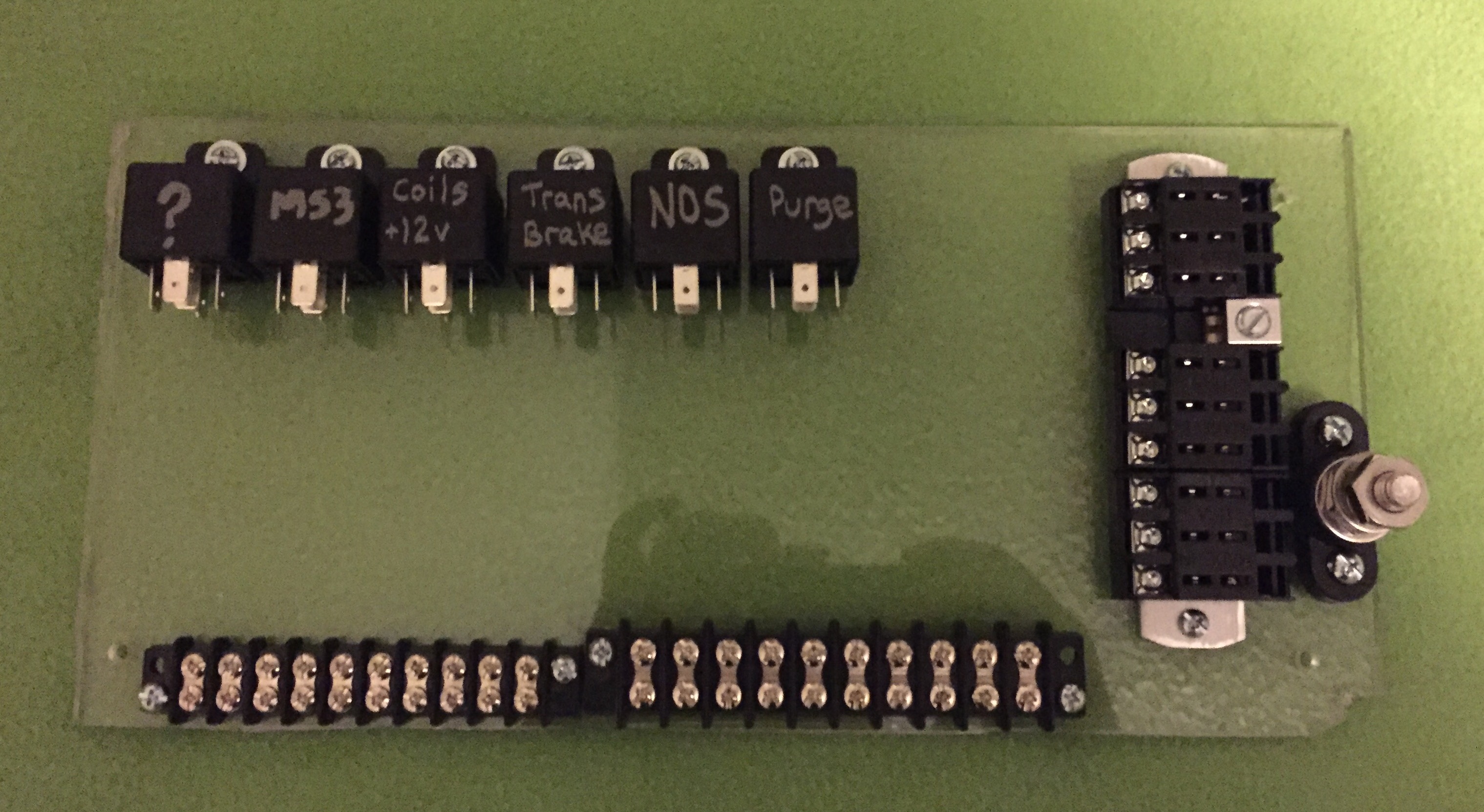
With the components mounted, it was time to begin wiring. I used 10 AWG stranded wire to provide power to the relays that are switching higher-amperage circuits. I also used the 10 AWG wire to connect the relays’ outputs to the #8 screw-terminals. I used 16 AWG stranded wire for every other connection on the board.
The wiring incorporates a few extras things I needed:
- The trans-brake, nitrous, and purge relays’ coils only have 12-volt power when the ignition relay/switch is on. Since these relays are controlled directly by the ECU, there’s a chance that the 12-volts to power the relay coils could backfeed into the ECU and prevent it from shutting off when the ignition switch is turned off. To prevent that, it’s important to kill the power to the relay coils when the ignition/ECU is shut off.
- The relay marked “MS3” powers the MegaSquirt Pro ECU exclusively. It sources 12-volts directly from the battery’s positive terminal instead of from the fuse block. This is to help ensure the ECU gets a clean power-source.
- The “?” relay is used to provide a throttle-position signal to the ECU. Since this car is carbureted, it doesn’t have a throttle-position sensor. However, in order for certain ECU features to work, it needs to at least read some change in throttle position. This relay’s NC post will connect to a sensor ground on the ECU and the NO post will connect to the ECU’s +5 volt reference signal. The relay is triggered by a wide-open-throttle switch on the carburetor. This will allow the ECU to determine whether the throttle is wide-open or not, which allows the nitrous and launch-control to activate properly.

What I would do differently
This was my first-time designing and building a panel of this nature. Overall, it came out alright. It will definitely serve its purpose for many years to come. However, there’s a few things I would do differently:
- Give myself more room – An extra inch on each of the panel’s dimensions would have helped quite a bit. 10 AWG wire is tough to work with in tighter spots like this. The wiring ended up being a little messier than I anticipated.
- Buy better quality tools – I’m using a regular old pair of Strippers/Crimpers. While the connections all came out fine, a quality set of crimpers would have made the process a lot more efficient. Not to mention, my hands were sore by the time I finished crimping everything.
what’s next?
Up next, I’ll install the panel in the car and begin wiring all of the major components. I’ll also install the MegaSquirt Pro ECU and build the wiring harness for the engine.